Assembling the flow cell from components
- Mechanical assembly
- Using a torque wrench properly
Ensure you have the following components:
Parts
- 2 brass current collectors
- 1 cell assembly tool
- 2 cut electrodes
- 3 cut membranes
- 4 cut tubing
- 2 flow frames
- 2 grafoil current collectors
- 2 inner gaskets
- 4 M6 fasteners
- 2 outer gaskets
- several cm polypropylene packing tape
Tools
- 1 10 mm socket - To fit torque wrench
- 1 5mm hex key
- 1 torque wrench - to accept 5 mm allen key or 10 mm hex socket
Step 1: Attach the tubing to the barbed fittings
Take the two flow frames and attach one piece of cut tubing to each barb. It should be a tight fit. You will only have to do this once.
Step 2: Insulate the bolts with packing tape
Wrap polypropylene packing tape around the shafts of the bolts, leaving the final 1 cm of threads exposed.
Note
This prevents accidental short circuits of the cell from the bolt shafts contacting the grafoil.
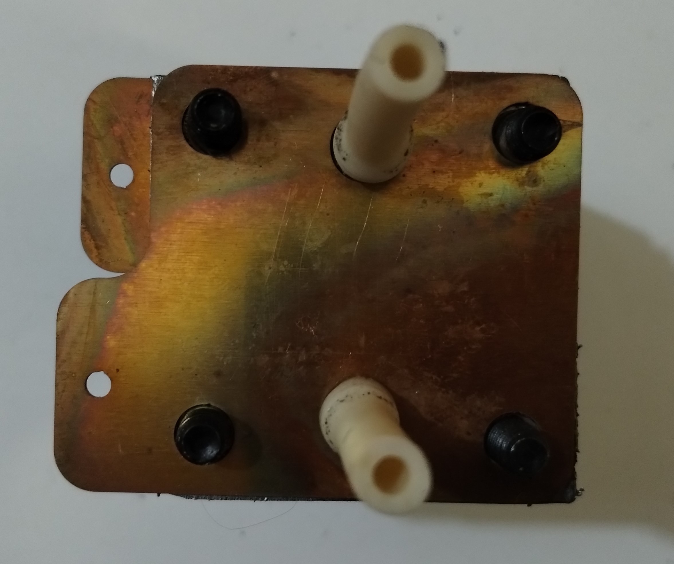
Step 3: Insert the four bolts into positive endplate
Gather the M6 fasteners.
Take one endplate and insert the four M6 x 35 mm hex socket cap bolts with washers. This will be the positive endplate.
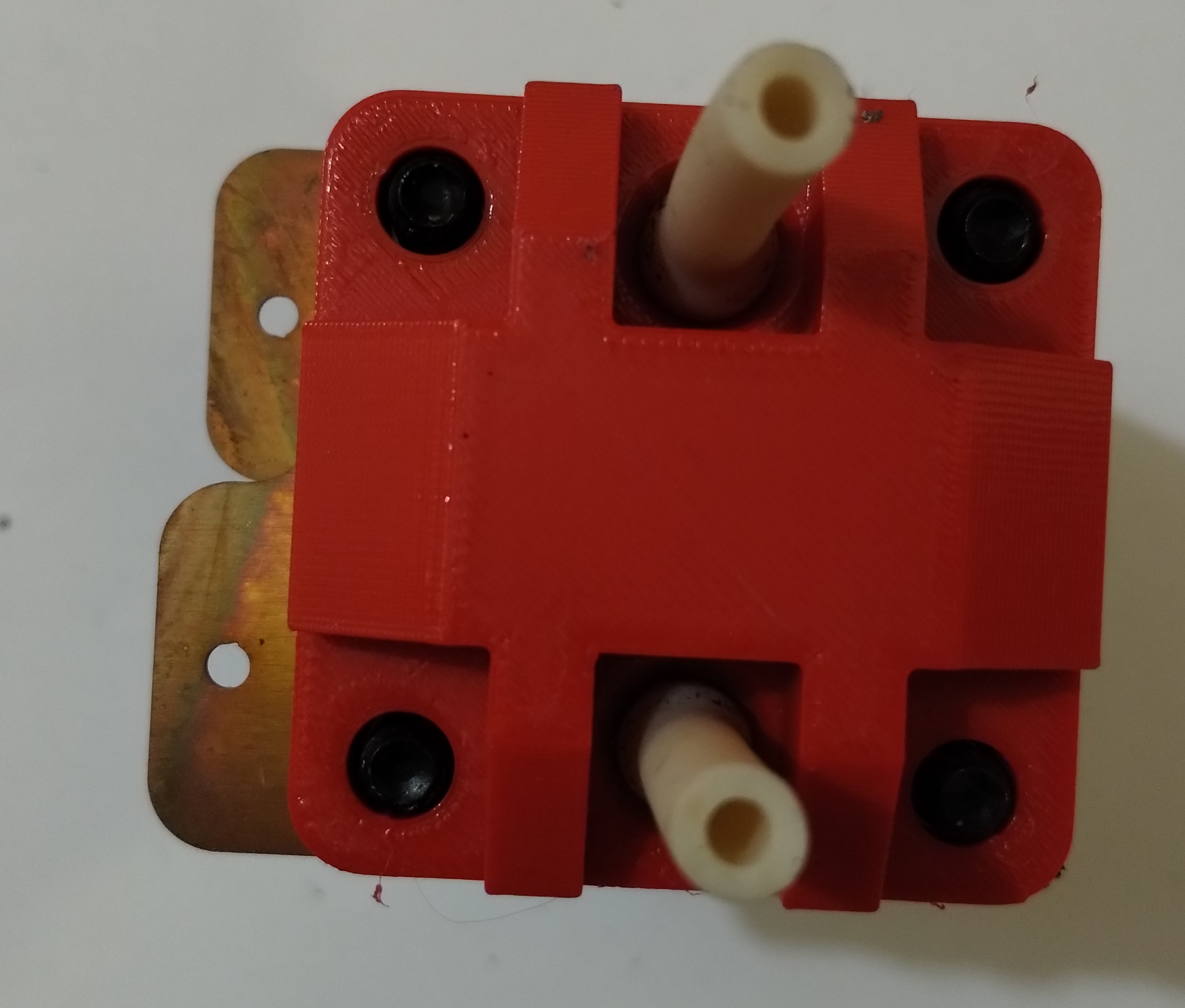
Step 4: Place the endplate on the cell assembly tool
Take the cell assembly tool and place the endplate on it so that the exposed bolt threads point up.
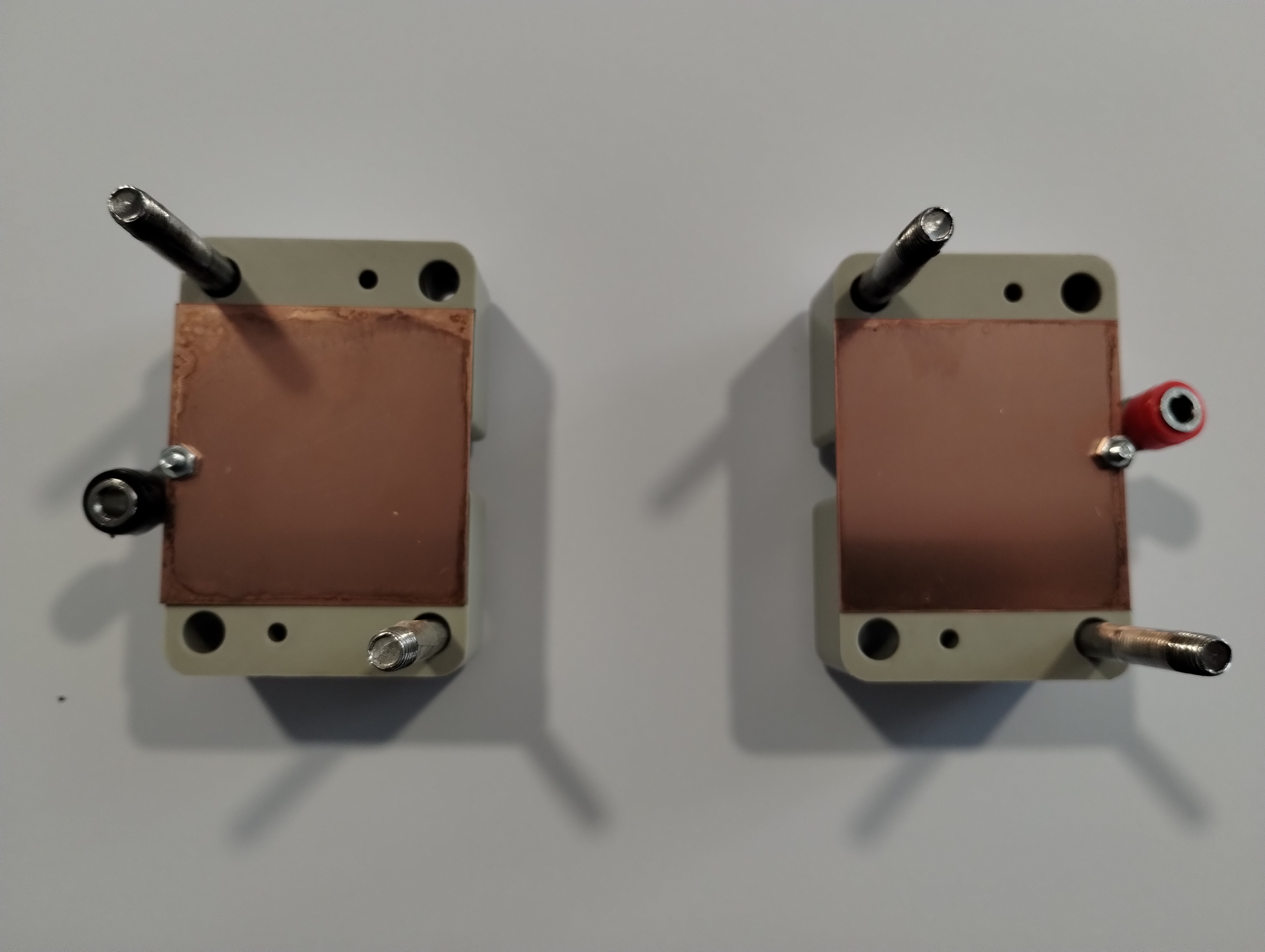
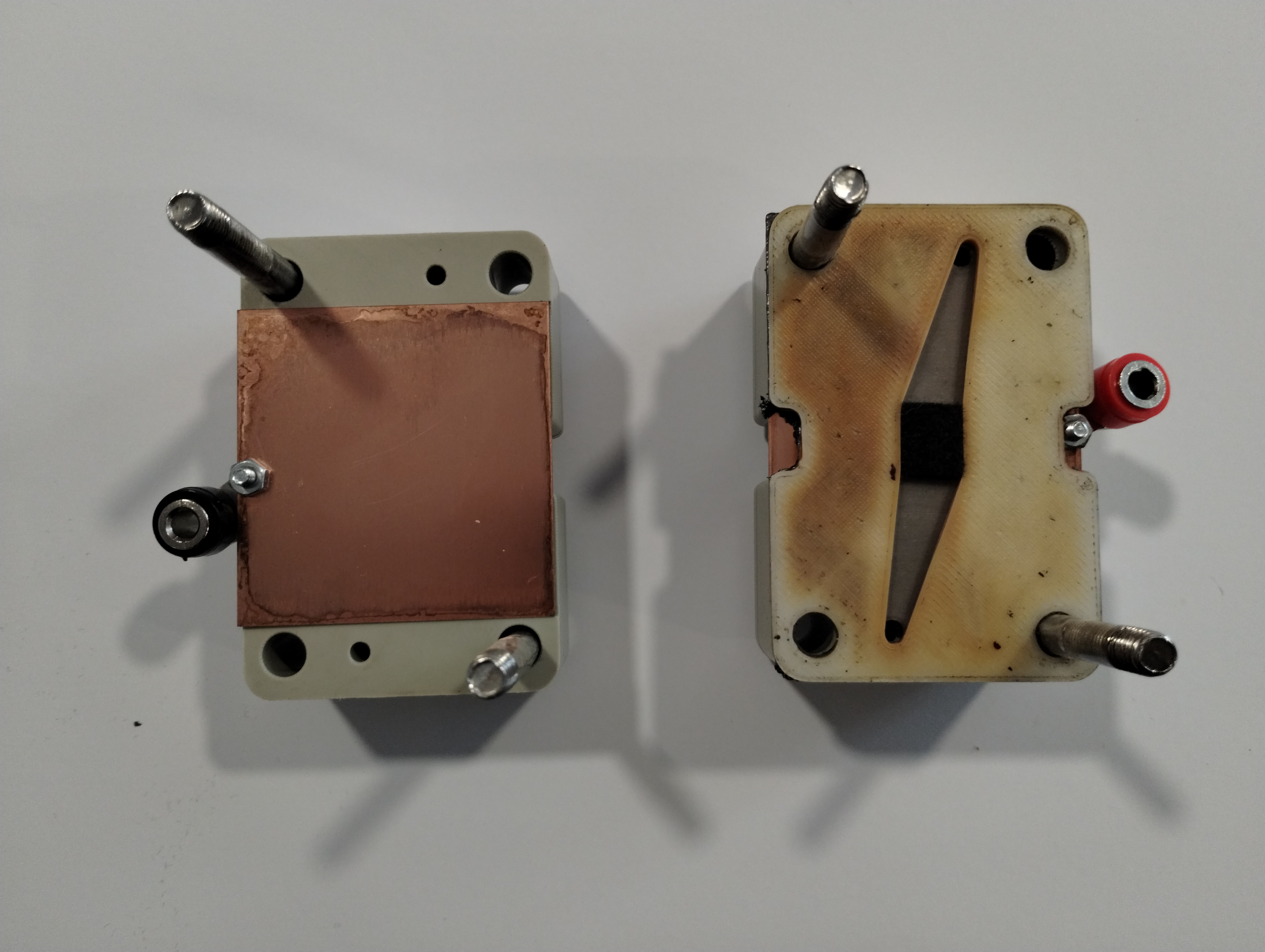
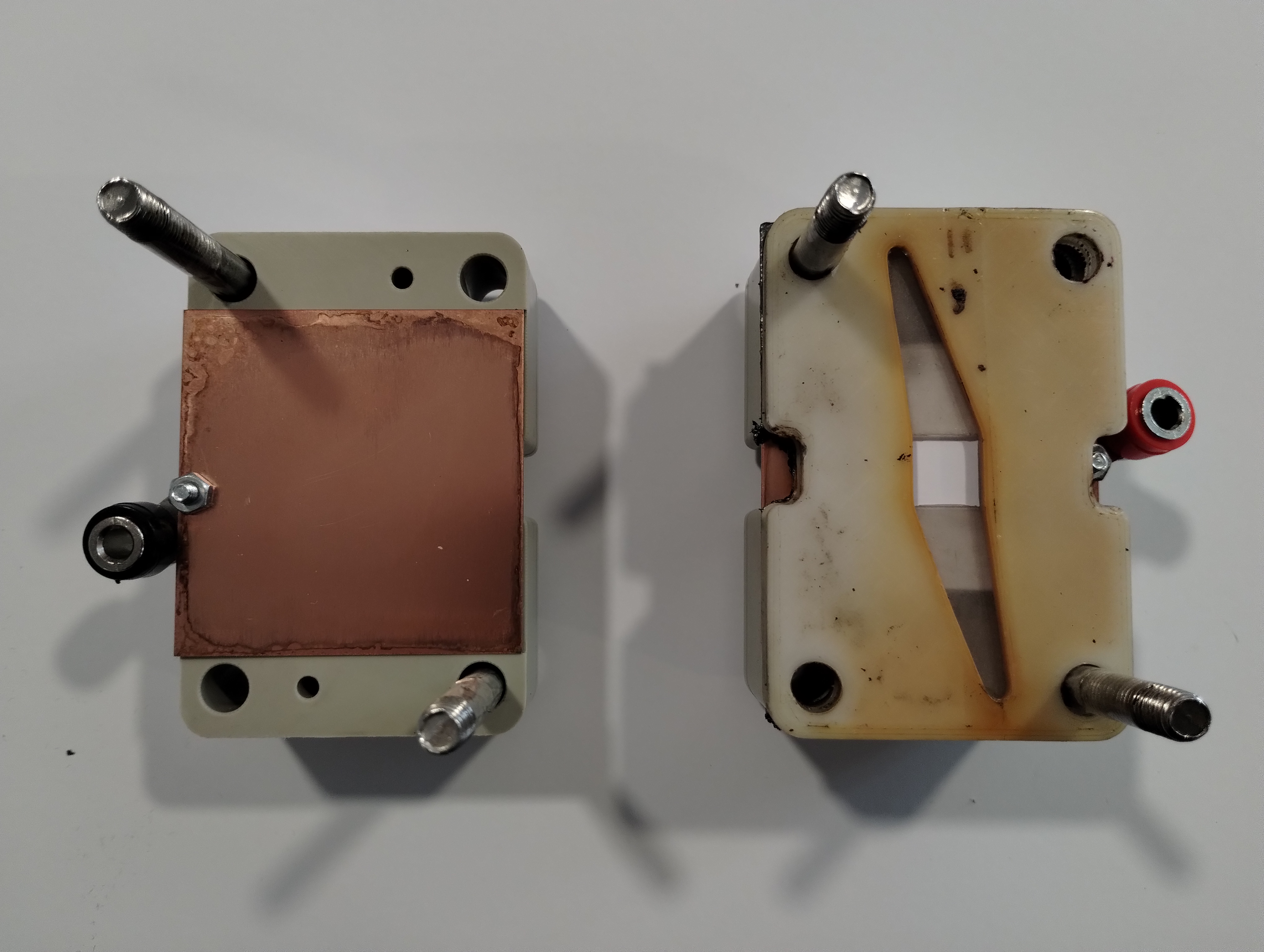
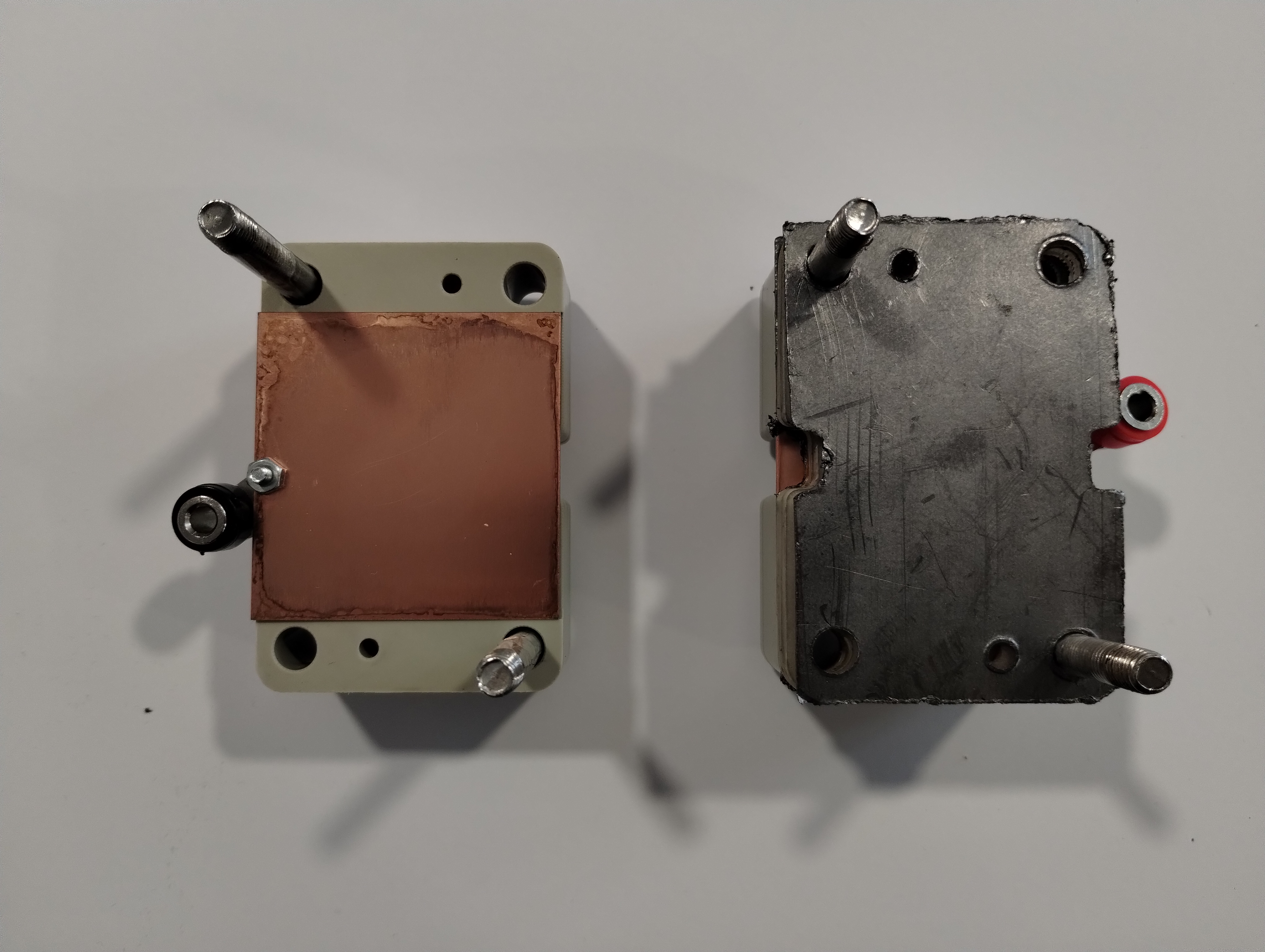
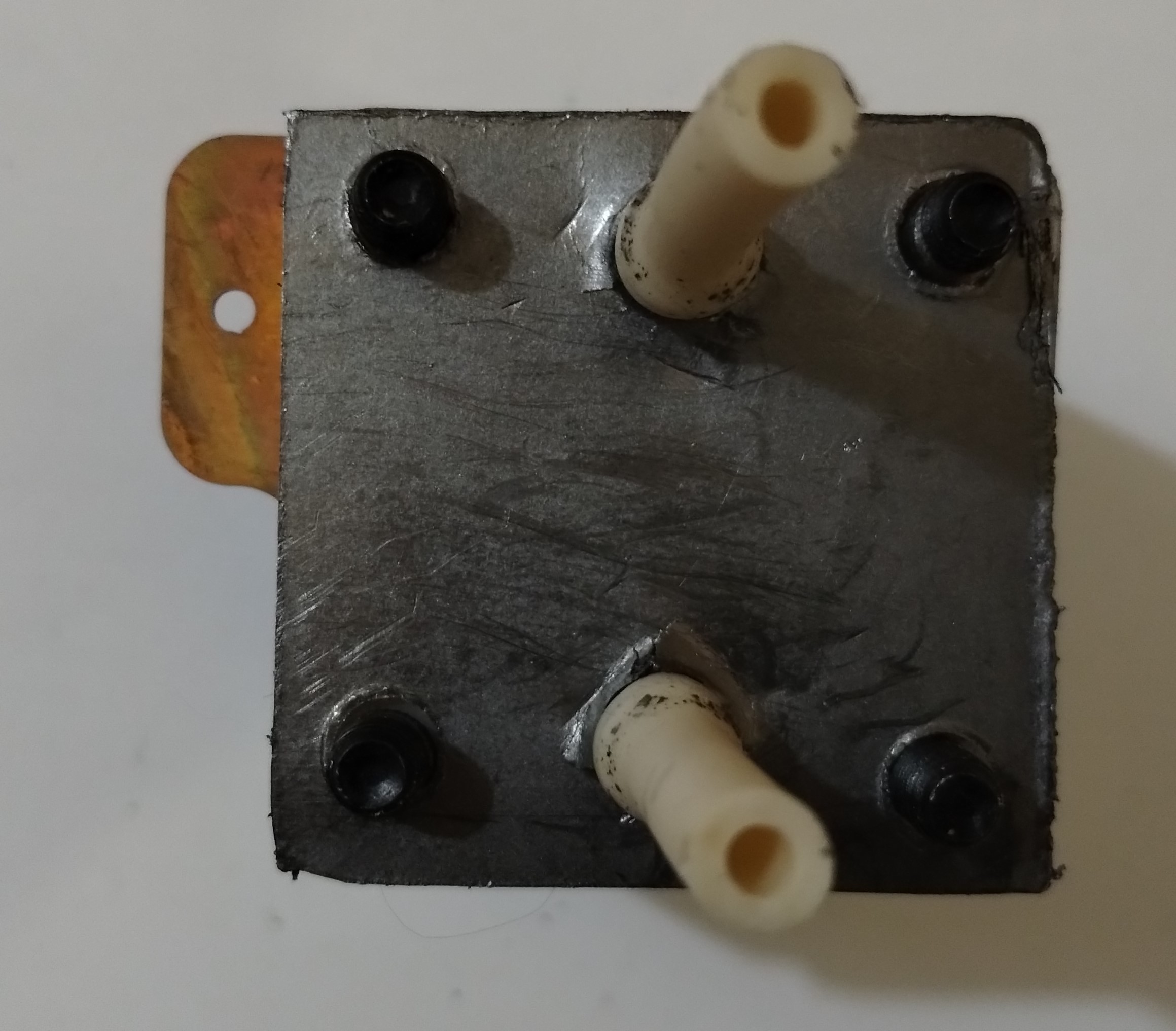
Step 5: Add the brass current collector
Make sure the large tubing holes of the current collector align with the endplate.
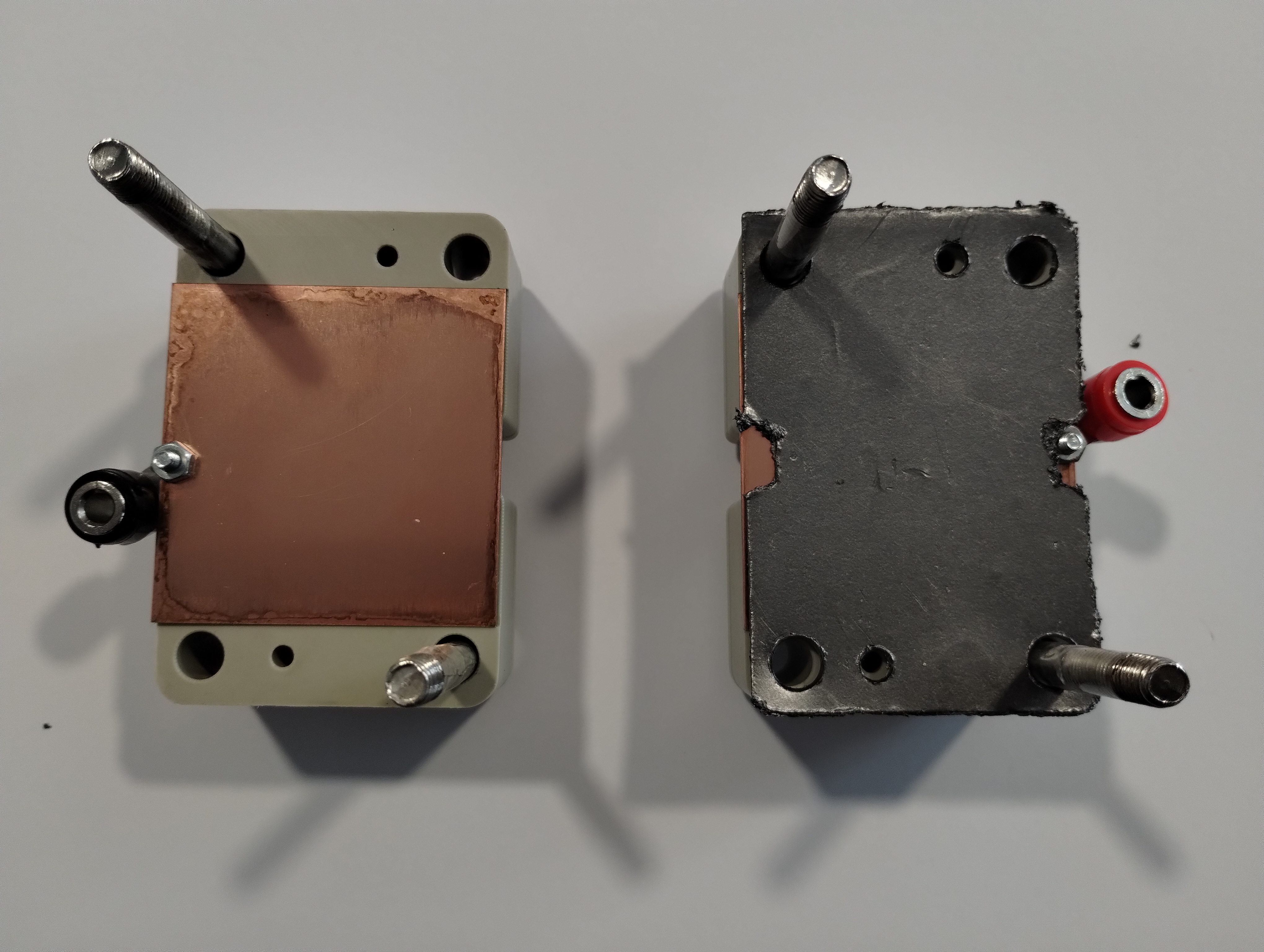
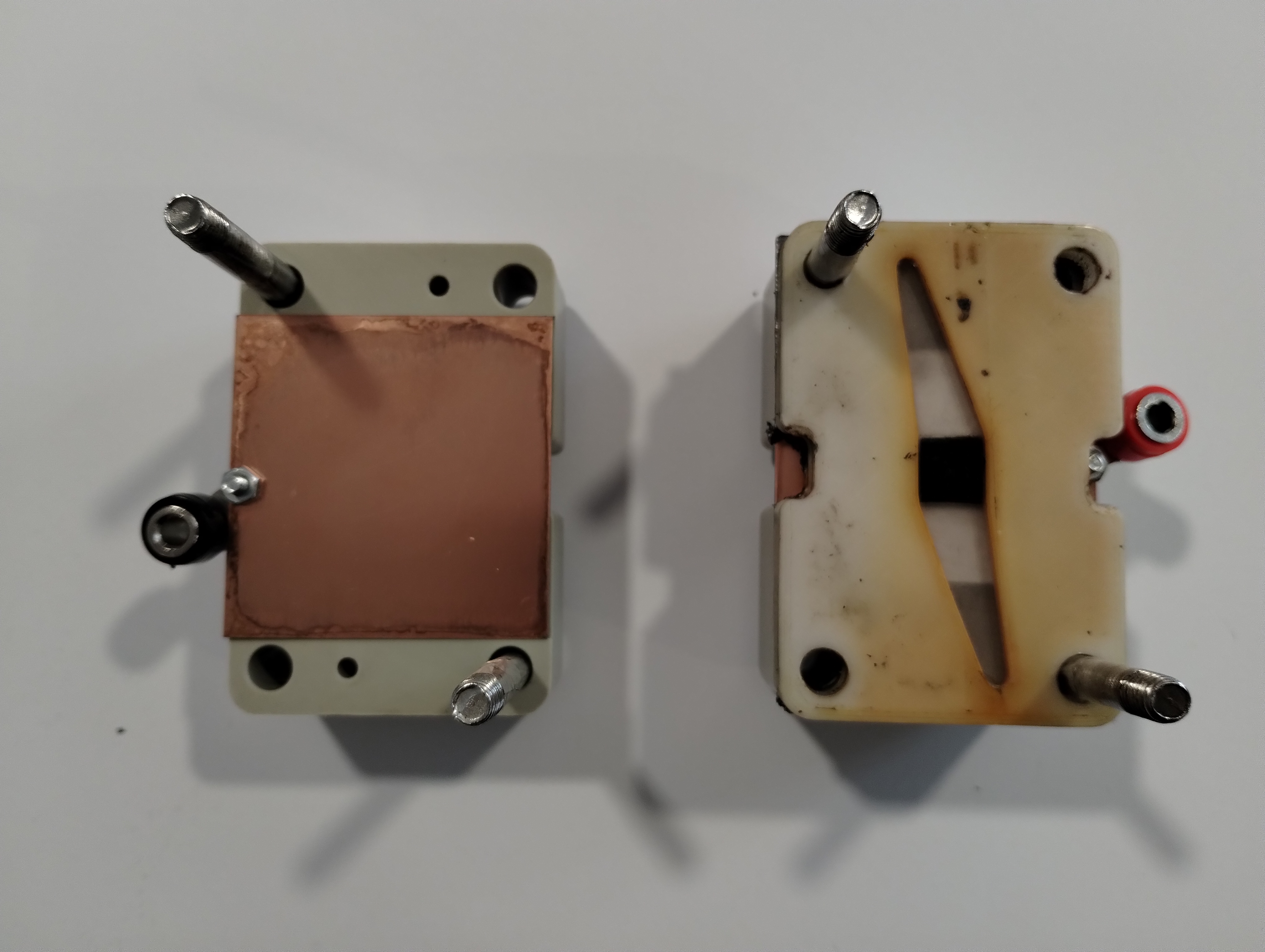
Step 6: Add the negative grafoil current collector
Make sure the large tubing holes of the grafoil current collector align with the brass current collector.
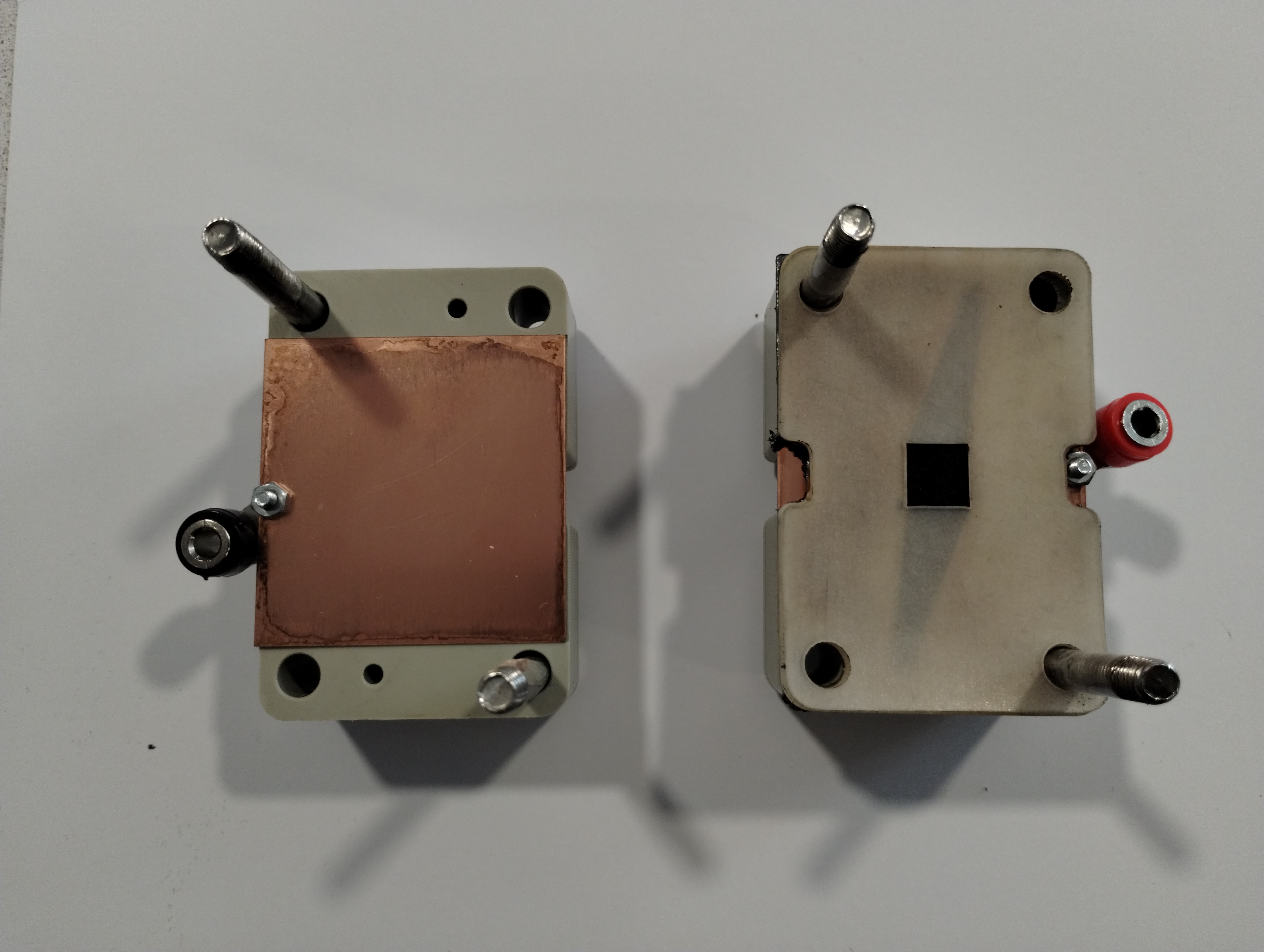
Step 7: Add the negative outer gasket
Place one outer gasket on top of the assembly, using the bolts to guide the gasket and align it with the fluid holes in the cell body.
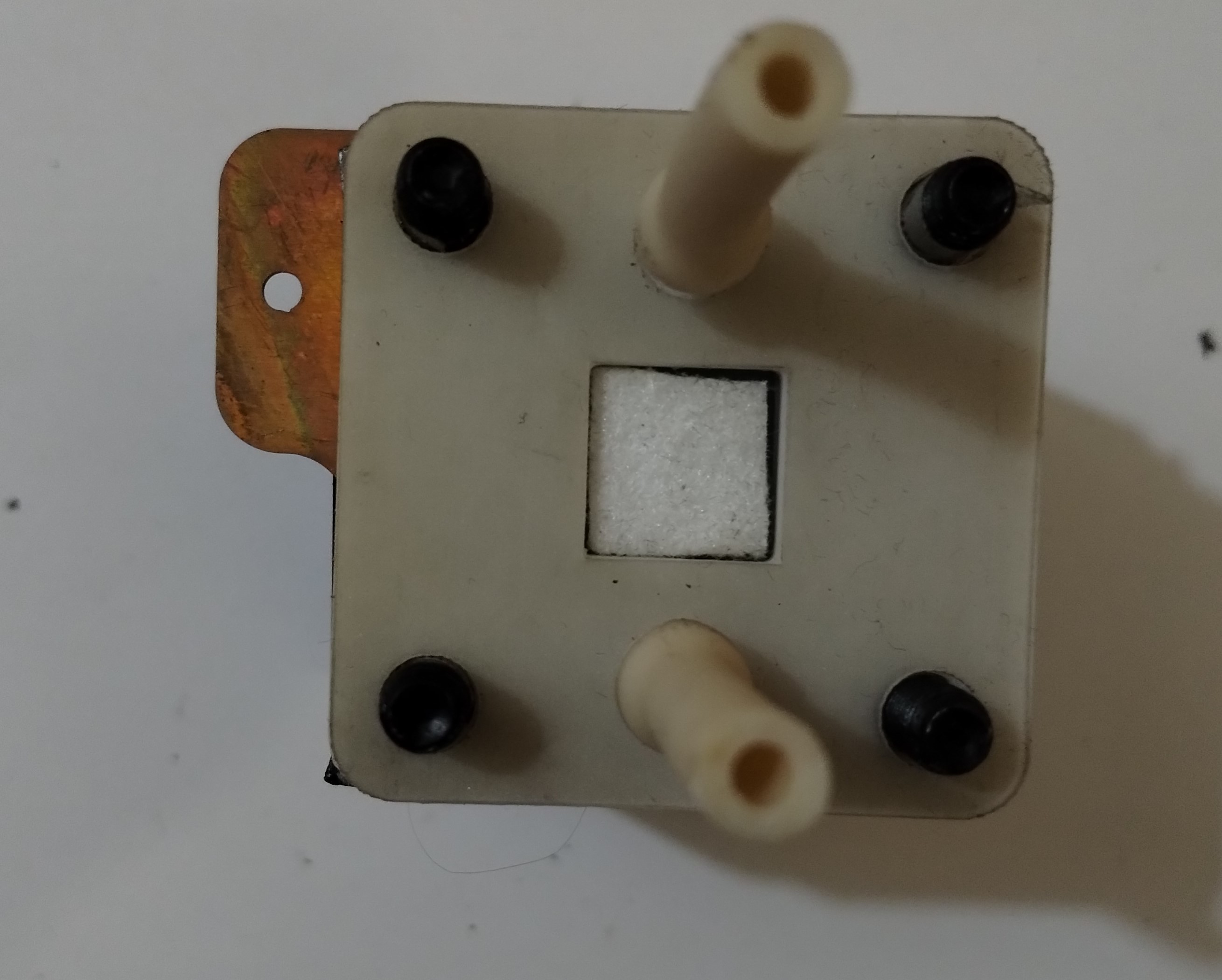
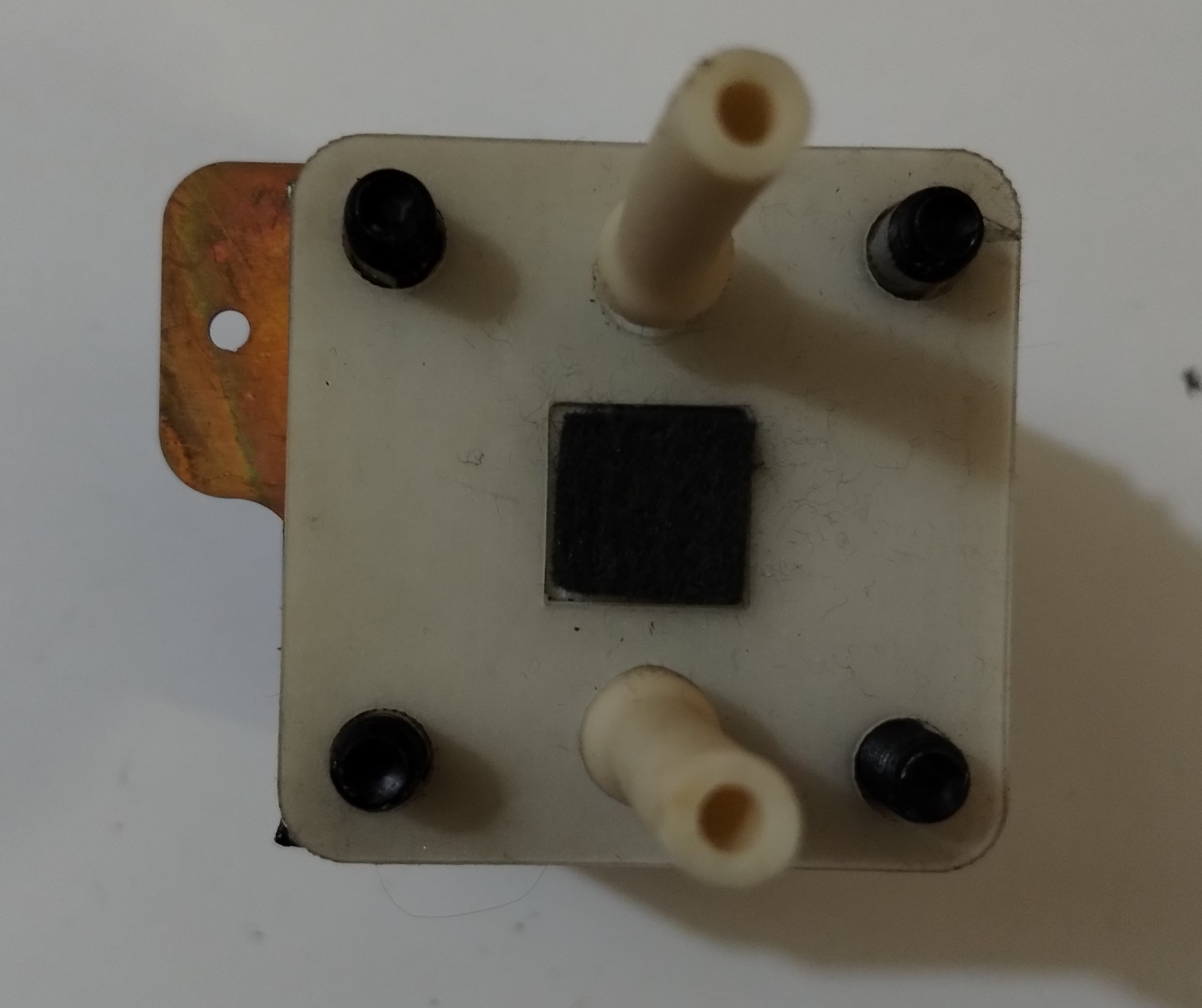
Step 8: Add the negative flow frame
Place one flow frame on top of the assembly, with the barbs and tubing facing downward into the cell assembly tool.
Help Block
The total combined thickess of the flow frames and (compressed) gaskets is key to achieving the desired results! There are multiple thickness options in the flow-frames folder and custom thicknesses can be genererated from the FreeCAD files. The graphite felt should be compressed to 70% of it's original thickness. The compression is fixed by the combined total thickness of the flow frame and two gaskets.
Step 9: Add the negative graphite felt
Place one graphite felt on top of the assembly.
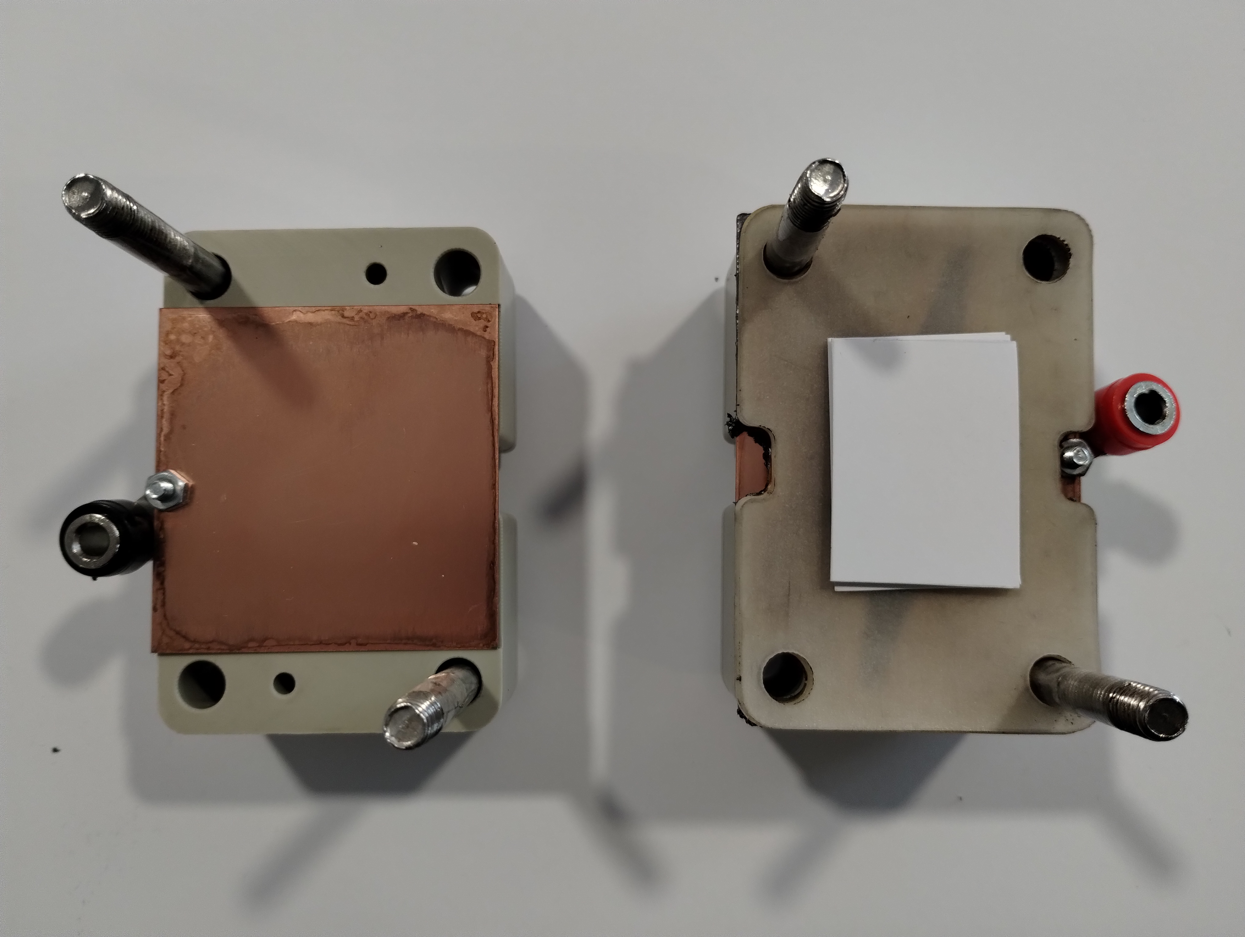
Step 10: Add the negative inner gasket
Take one inner gasket and add it to the assembly.
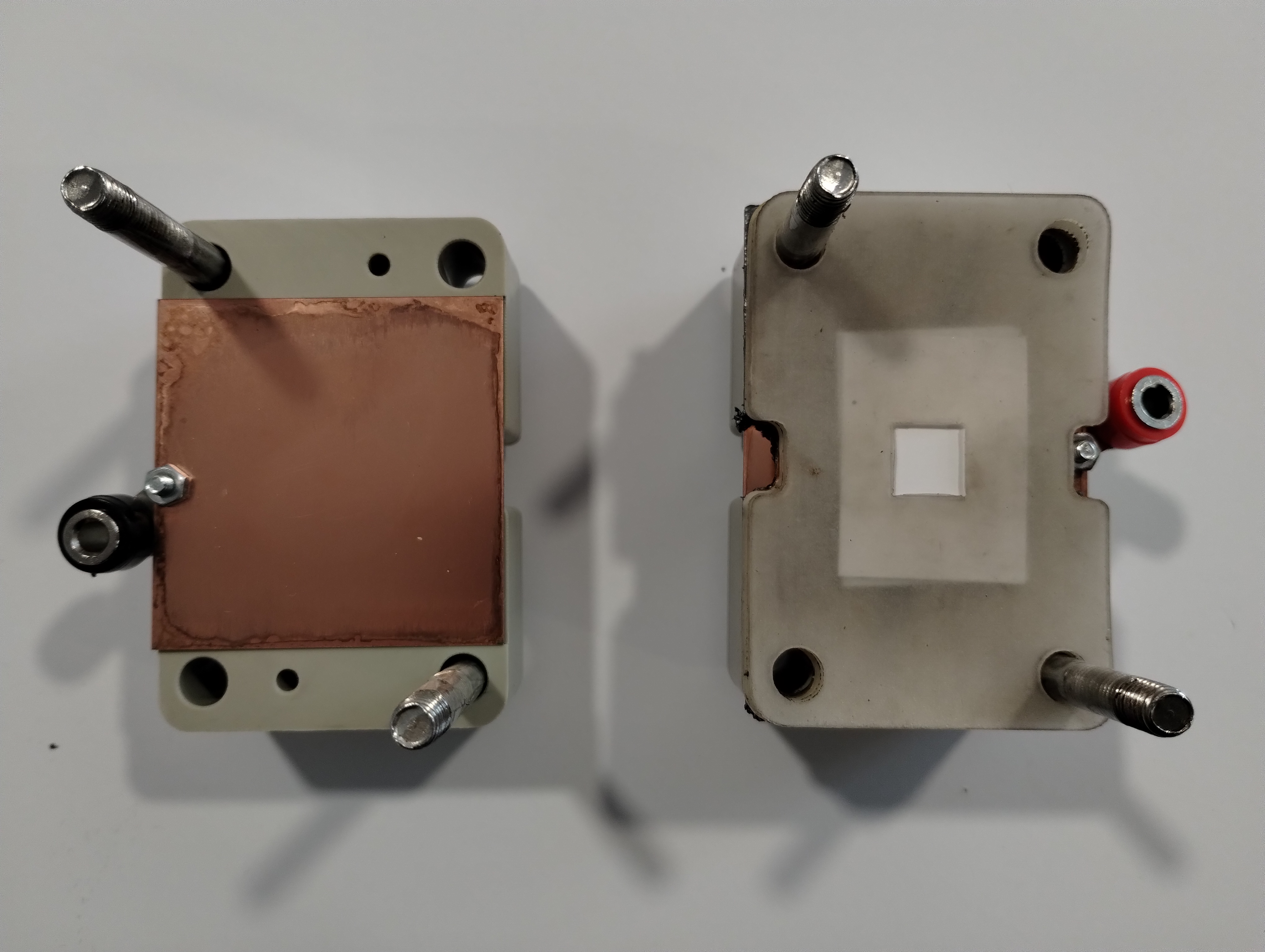
Step 11: Add the membranes
Take the three cut membranes and add them to the assembly.
Step 12: Add the positive inner gasket
Take one inner gasket and add it to the assembly.
Step 13: Add the positive flow frame
Place one flow frame with tubing on top of the assembly, using the bolts to guide the flow frame.
Step 14: Add positive outer gasket
Place one outer gasket on top of the assembly, using the bolts to guide the flow frame.
Step 15: Add positive graphite felt
Place one graphite felt on top of the assembly, using the bolts to guide the flow frame.
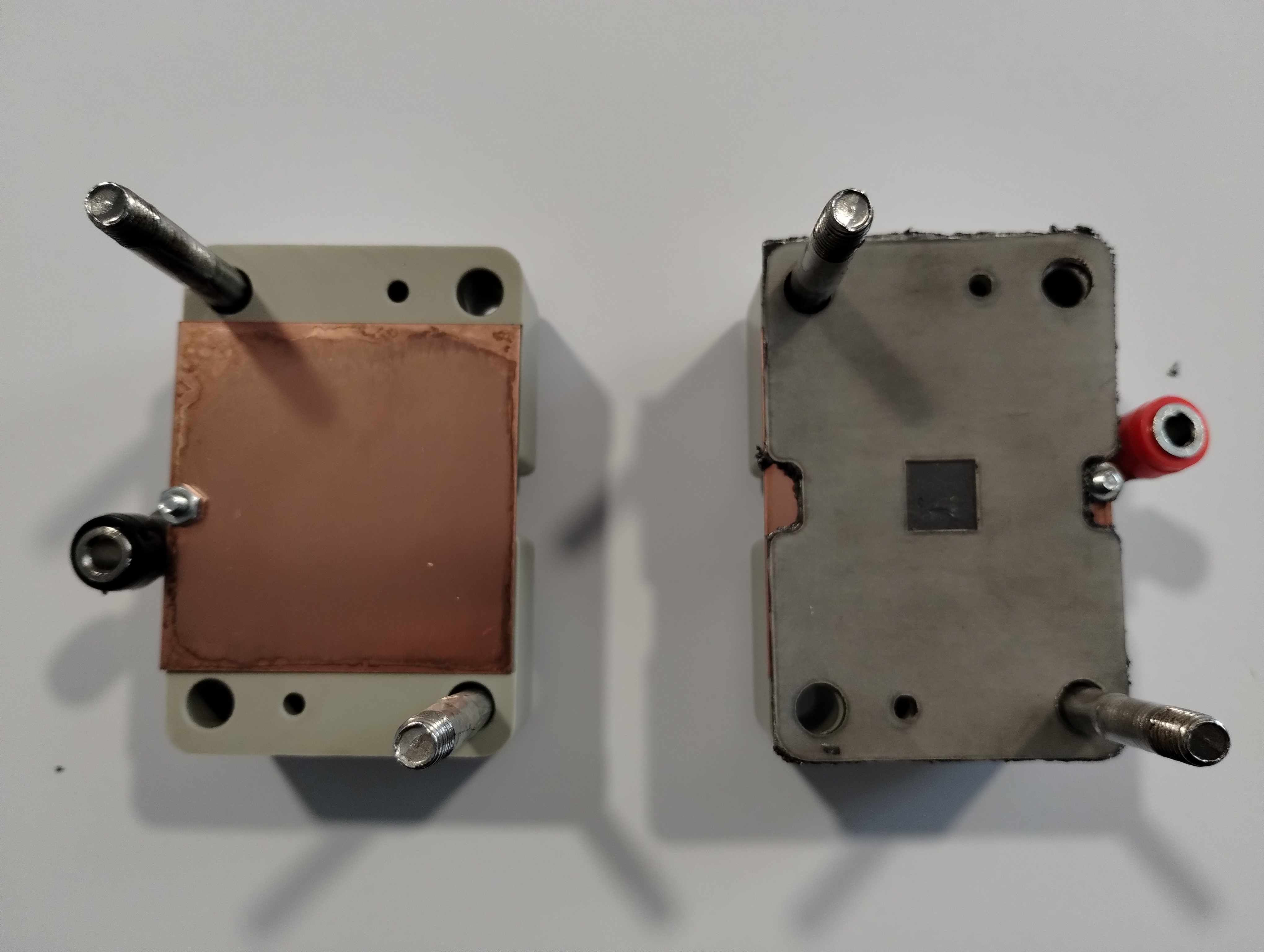
Step 16: Add the positive grafoil current collector
Place the positive grafoil current collector over the flow frame.
Step 17: Add the positive brass current collector
Place the positive current collector on the cell as shown so the tab is facing opposite the negative current collector tab.
Step 18: Add the positive endplate
Place the second cell body (with barbs and brass plate installed) on top of the assembly and ensure all fluid holes are aligned.
Step 19: Tighten the bolts
Hand-tighten four M6 nuts with washers onto the exposed threads of the bolts in order to lightly compress the cell and hold all the components in place.
Progressively tighten the bolts to 5 N⋅m in a 4-bolt flange pattern using a torque wrench fitted with a 10 mm socket and a 5mm hex key
Note
Progressively tightening using a flange pattern is important to evenly compressing the cell and ensuring leak-free operation
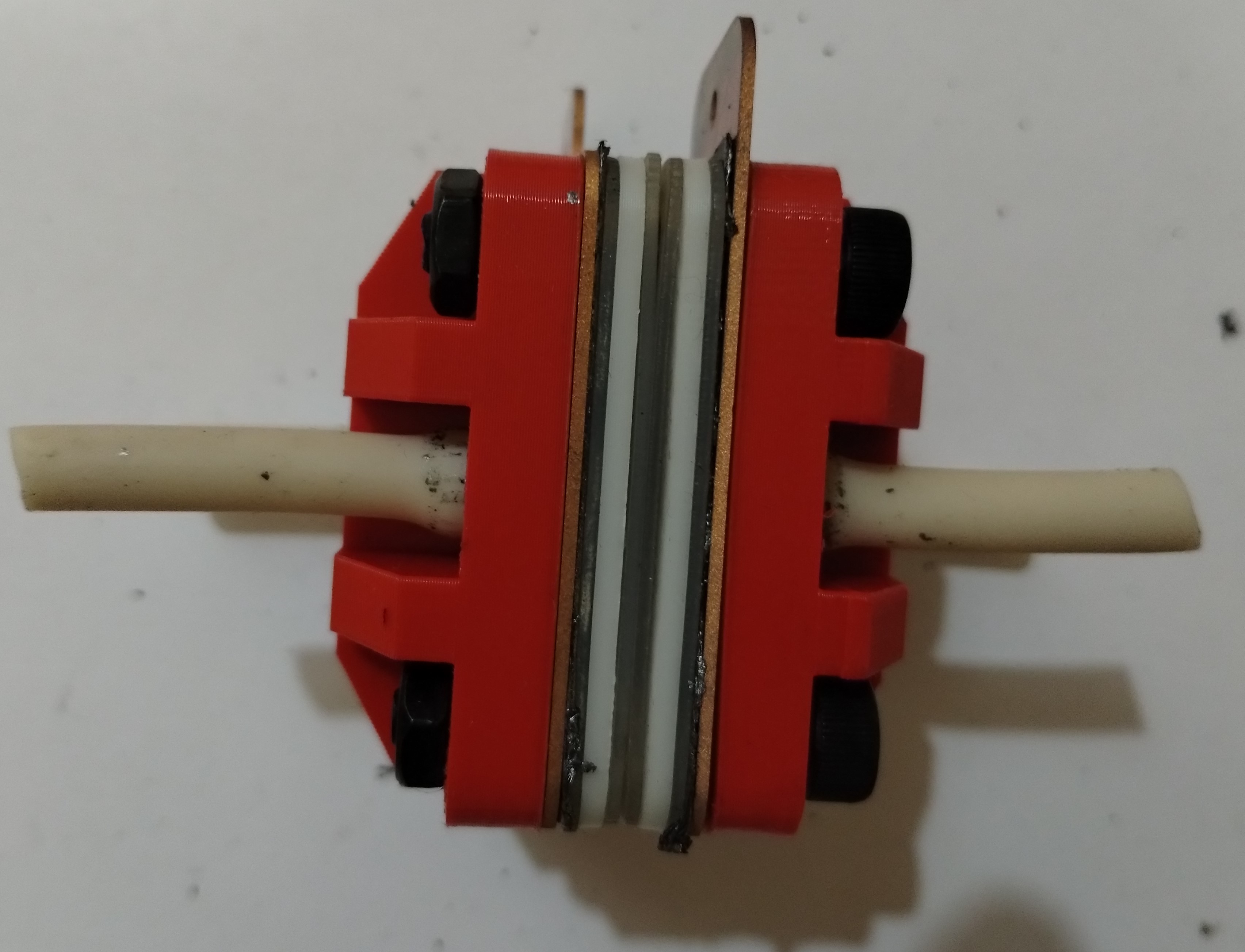
Nice work, now you have an assembled flow cell!