Preparing the pumps and power electronics
- Electronics breadboarding
- Flashing firmware to an Arduino
Parts
- 1 24 V DC power source
- 1 Arduino UNO R3 - or equivalent microcontroller that can output two independent 5V PWM signals and connect to PC over USB serial
- 1 jig
- several male-to-male breadboard jumper cables
- 2 peristaltic pumps with correct tubing
- 4 self-tapping screws
- 1 USB A-to-B cable
Tools
- 1 PC - Must be able to flash firmware to microcontroller and connect over USB serial to microcontroller and potentiostat
- 1 potentiostat - preferably the MYSTAT
System overview
A PC communicates with both a charging/discharging device (typically a potentiostat) as well as an Arduino UNO R3. These documents assume the use of a MYSTAT potentiostat and it's modified control software.
The Arduino is connected to two peristaltic pumps which have internal stepper motor drivers, and are powered by a 24 V DC power source. To know the flowrate (in mL/min) of the peristaltic pumps, a separate measurement is required (like dispensing water into a graduated cylinder).
We use the open-source MYSTAT (with our own modifications to the control software), but any equivalent potentiostat or battery cycler will do. Our pump control system is based on the MYSTAT software, though, and can be used without the MYSTAT present.
With this hardware configuration, the MYSTAT software then allows for entire control of this electrochemical system: the applied currents and voltages as well as the speeds of the electrolyte pumps.
Step 1: Flash firmware to microcontroller
Using the Arduino IDE with the elapsedMillis library installed, upload the following code to the Arduino. The location of the code in the repository is here
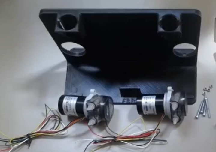
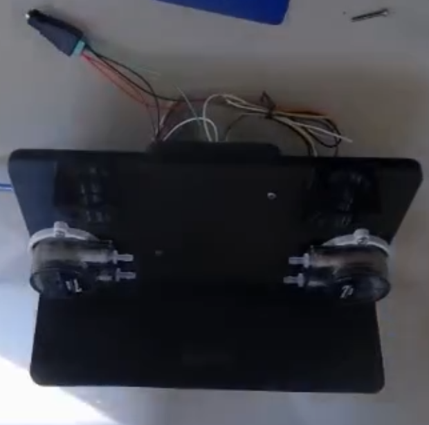
Step 2: Add pumps to jig
Insert the two peristaltic pumps with correct tubing into their holders in the as shown:
Step 3: Add case, Arduino UNO to the jig
There are holes for the for the Arduino and its case on the back of the jig . Using four self-tapping screws inserted from the front of the jig, attach the case and Arduino to the jig.
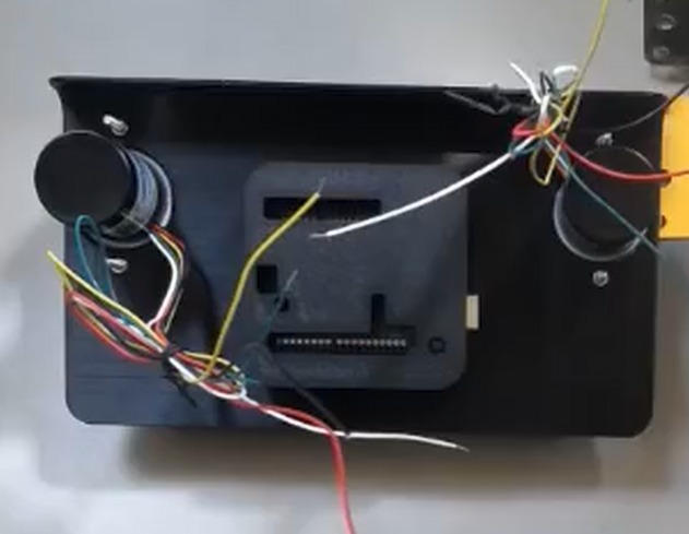
Note
The reset button is placed with the large end inside the case, as visible in the original designer's photos
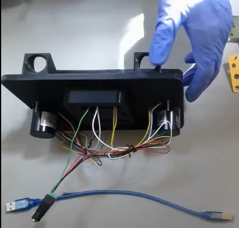
Step 4: Connect cables between Arduino, motors, and power supply
Using male-to-male breadboard jumper cables connect according to the below diagram:
Positive pump:
- Red wire to DC power jack positive terminal
- Black wire to DC power jack negative terminal
- Yellow wire (PWM speed control) to Arduino pin 2
- White wire (Tacho / speed measurement) to Arduino pin 10
- Green wire (reverse) to Arduino GND
Negative pump:
- Red wire to DC power jack positive terminal
- Black wire to DC power jack negative terminal
- Yellow wire (PWM speed control) to Arduino pin 3
- White wire (Tacho / speed measurement) to Arduino pin 11
- Green wire (reverse) leave unconnected
Misc.
- Connect DC power jack negative terminal to Arduino GND
Step 5: Connect microcontroller to PC and test pumps
We are using the MYSTAT potentiostat and have modified the software to be able to control the pump speeds. If you have a different potentiostat, you can still use the MYSTAT software to control your pumps without having a MYSTAT connected.
Plug in the 24V power source to the H-bridge. Connect the Arduino to the PC with a USB A-to-B cable
Run the MYSTAT modified control software.
Connect to the Arduino through the MYSTAT GUI. Briefly test each pump to make sure it spins (it can spin for a couple seconds dry without issues).