Assembling the jig with electronics and flow cell

- Mechanical assembly
Gather the following components:
Step 1: Add reservoirs to jig
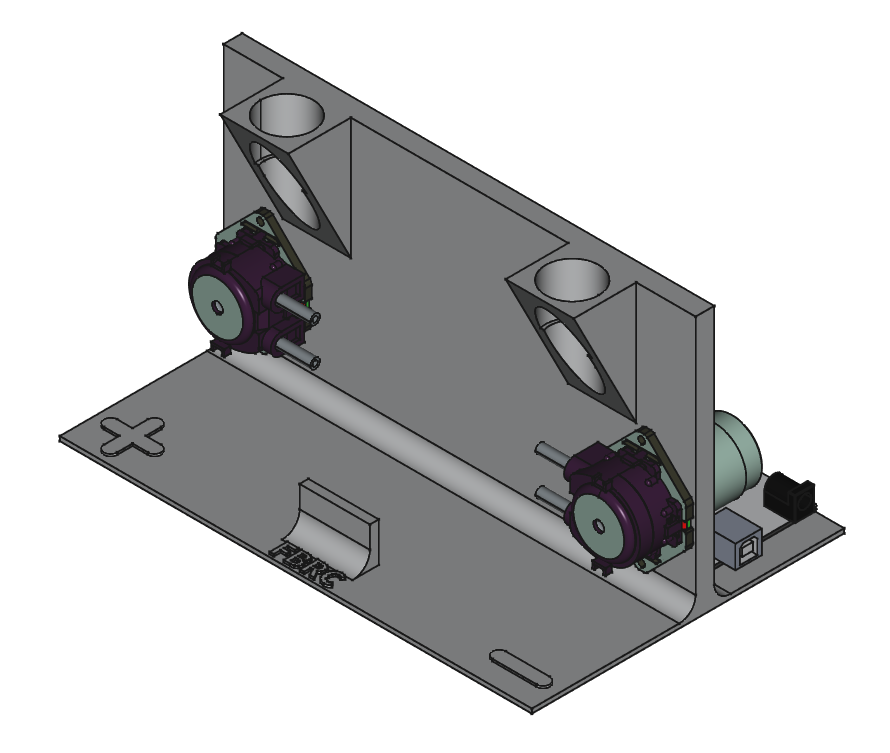
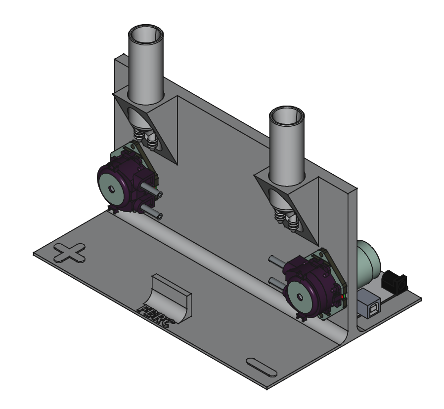
Insert the two reservoirs into the jig with pumps and power electronics as shown:

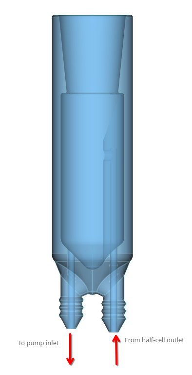
Warning One barb on each reservoir is slightly longer than the other barb. This longer barb is for electrolyte returning to the reservoir from the cell, and there is an internal channel in the reservoir that returns electrolyte to the top of the reservoir. The short barb is for electrolyte going to the pumps from the reservoir, and it draws electrolyte from the bottom of the reservoir.
!!
Step 2: Add cell to jig and connect to tubing
Take the assembled flow cell and place it into the jig, connecting the tubing as described and shown:
Take the rest of the cut tubing and connect the lengths as so, for both positive and negative half-cells: - pump outlet to inlet of cell (on bottom) - outlet of cell (on top) to long barb on reservoir - short barb on reservoir to pump inlet

Warning
Avoid creating kinks and sharp bends in the tubing when assembling the cell. This can create issues with electrolyte flow.
Warning
Electrolyte flow must flow from bottom of the cell upwards to top, in order to clear out gas bubbles from the cell and ensure good liquid electrolyte flow
This makes an assembled test jig.
