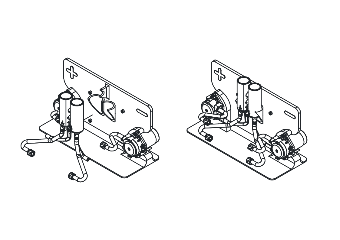
Preparing the jig with pumps and power electronics
- Soldering
- Flashing firmware to an Arduino
Parts
- 1 24 V DC power source
- 2 4 cm cut tubing
- 1 Arduino UNO R3 - or equivalent microcontroller that can output two independent 5V PWM signals and connect to the computer over USB serial
- 1 assembled jig
- 1 combined reservoir with tubing
- 1 DC power jack
- 2 F-31 Luer Lock Adapters
- 8 M3x35mm socket cap bolts and nuts
- 2 peristaltic pumps with correct tubing
- 1 pump controller case parts
- 1 USB A-to-B cable
Tools
- 1 computer - Must be able to flash firmware to microcontroller and connect over USB serial to microcontroller and potentiostat
- 1 potentiostat - preferably the MYSTAT
- 1 soldering iron
System overview
A computer communicates with both a charging/discharging device (typically a potentiostat) as well as an Arduino UNO R3. These documents assume the use of a MYSTAT potentiostat and it's modified control software.
The Arduino is connected to two peristaltic pumps which have internal stepper motor drivers, and are powered by a 24 V DC power source. To know the flowrate (in mL/min) of the peristaltic pumps, a separate measurement is required (like dispensing water into a graduated cylinder).
We use the open-source MYSTAT (with our own modifications to the control software), but any equivalent potentiostat or battery cycler will do. Our pump control system is based on the MYSTAT software, though, and can be used without the MYSTAT present.
With this hardware configuration, the MYSTAT software then allows for entire control of this electrochemical system: the applied currents and voltages as well as the speeds of the electrolyte pumps.
Step 1: Flash firmware to microcontroller
Using the Arduino IDE with the elapsedMillis library installed, upload the following code to the Arduino. The location of the code in the repository is here
Solder the wiring harness
Using a soldering iron, take the peristaltic pumps with correct tubing, DC power jack and solder them to the Arduino according to the following schematic:
Caution
Be sure to connect the Arduino ground to the power supply ground of the pumps so that the PWM and tachometer signals work properly
Assemble the pump controller case
Taking the soldered Arduino, pumps, and DC power jack, assemble them into the pump controller case parts as shown:
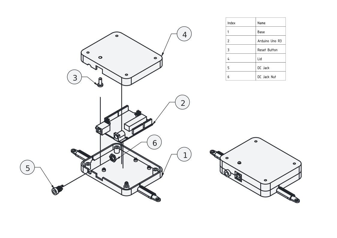
The pump wiring is fed through the long narrow slots in the pump controller case base so that it can be assembled into the case post-soldering.
Step 2: Add pumps and controller case to jig
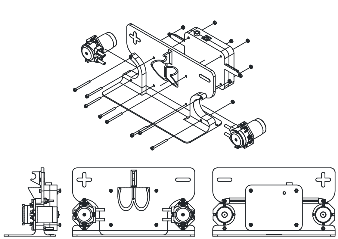
Insert the pumps into their holders in jig while aligning the pump controller case mounting holes with their matching holes on the jig. Fasten with eight M3x35mm socket cap bolts and nuts.
Note
The reset button is placed with the large end inside the case
Step 3: Connect microcontroller to PC and test pumps
We are using the MYSTAT potentiostat and have modified the software to be able to control the pump speeds. If you have a different potentiostat, you can still use the MYSTAT software to control your pumps without having a MYSTAT connected.
Plug in the 24V power supply cable to the jack on the case.. Connect the Arduino to the PC with a USB A-to-B cable.
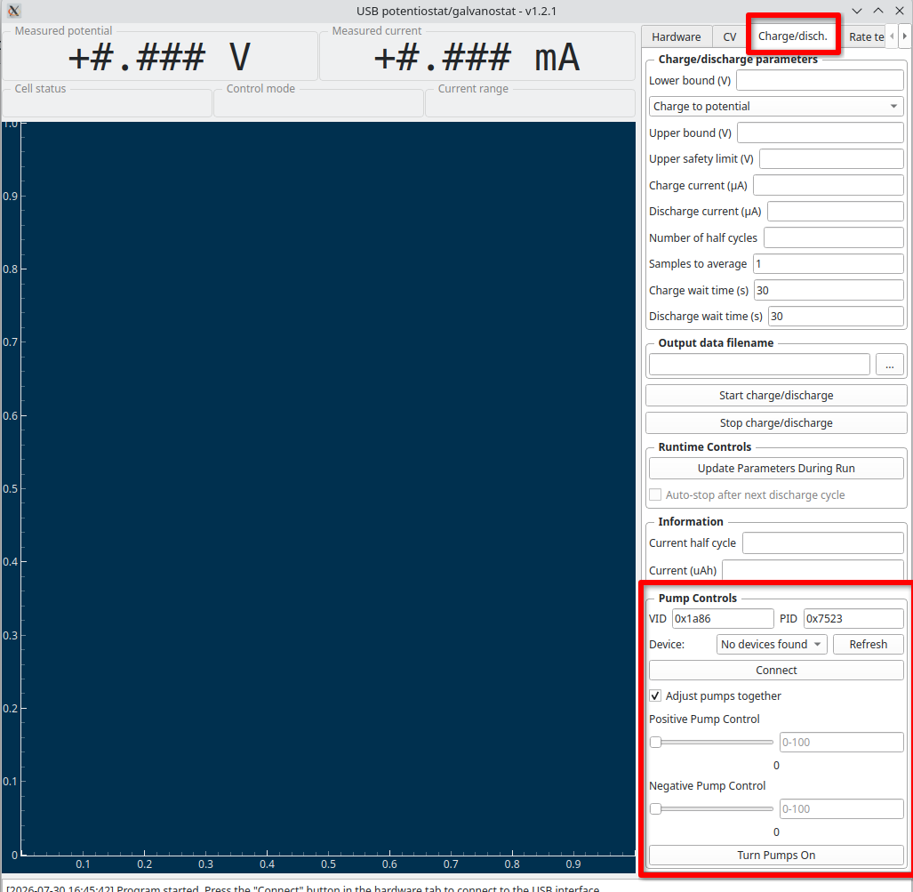
Run the MYSTAT modified control software.
Connect to the Arduino through the MYSTAT GUI. Briefly test each pump to make sure it spins (it can spin for a couple seconds dry without issues).
Step 4: Add tubing and connectors to top pump connections
Add two pieces of 4 cm cut tubing to the upper barbed fittings of each pump. Add a F-31 Luer Lock Adapter to the other end of each piece of tubing.
Note
The tubing here is shown bent according to it's final shape after cell assembly, this will happen naturally when the cell is installed.
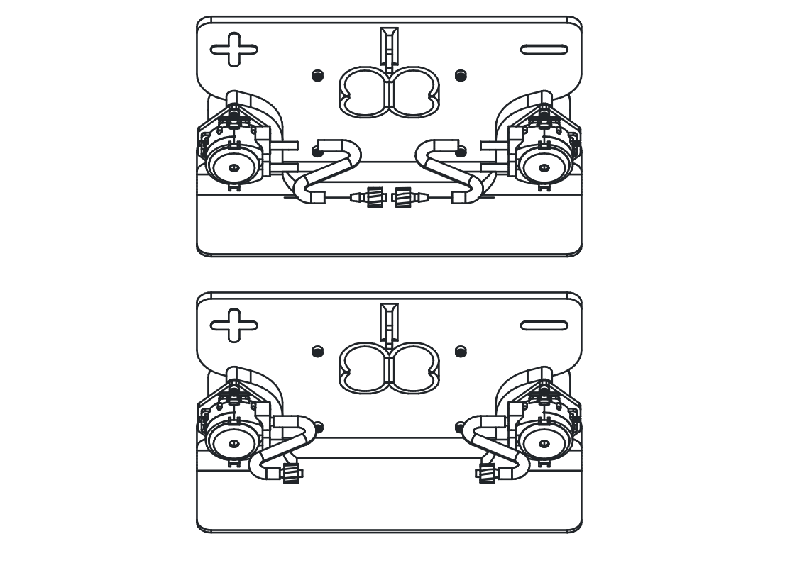
Step 5: Add reservoirs to jig
Insert the combined reservoir with tubing into the jig as shown, connecting the shorter tubing on the inner barbs of the reservoirs to the bottom connection of the pump. The reservoirs should "click" into place into the holding mechanism on the jig. The flexible tubing will eventually take on a shape similar to what is shown when the cell is installed.